Pinout
The screw terminal of WiCAN USB, position by position, and the termination resistor behind the TR position of the earlier boards.
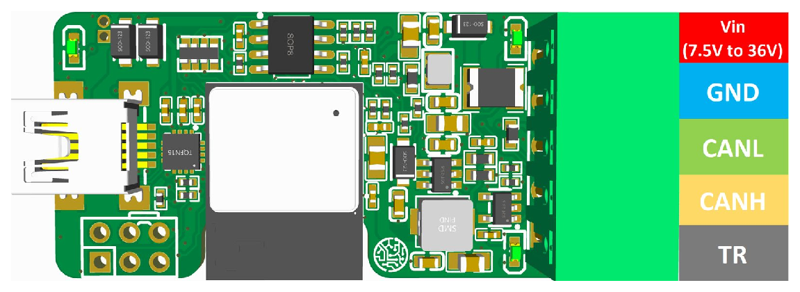
| Position | Connect to |
|---|---|
| VIN | The supply, 7.5 V to 36 V: a 12 V car battery, a 24 V truck, a bench supply. Leave it open when the USB cable powers WiCAN. |
| GND | The ground of the bus and of the supply. |
| CANL | The CAN low wire of the bus. |
| CANH | The CAN high wire of the bus. |
| TR (earlier boards) | Nothing, or CANH to switch in the 120 Ω termination resistor: its other end is wired to CANL inside. |
Boards with four positions have no termination inside: put a 120 Ω resistor across CANH and CANL when WiCAN sits at the end of a bus you build yourself. Hardware explains when a bus needs it, and covers power, the USB port and the LEDs.
Tapping a car's OBD port
Pin 6 is CAN high, pin 14 CAN low, pins 4 and 5 ground and pin 16 the battery, which can feed VIN. The WiCAN OBD pinout shows them.